Introduction
Tutorials
Improving a discharge simulation
TETRAD is software that models a geothermal reservoir. TETRAD uses measurements or estimates in the reservoir to calculate predicted conditions (like temperature and pressure) throughout the reservoir. It is then necessary to compare the predicted conditions to measured conditions to check the accuracy of TETRAD's model.
One way of doing this is to use measured conditions at the wellheads of reservoir wells. To do this:
Each well is assumed to be discharging at a steady flowrate and to have no secondary feedzones.
This tutorial shows how to use WellSim to create such TETRAD data tables for wells. Note that supplying TETRAD with such tables is optional; you can check the accuracy of the model in other ways.
To calculate a TETRAD data table, you specify a well geometry, a feedzone depth, formation temperatures and ranges of values of feedzone data. For each combination of the feedzone data, WellSim then calculates a BottomUp discharge simulation to find the corresponding wellhead conditions.
You can enter feedzone data separately for:
However, don't try too hard to guess expected values of feedzone data, usually just enter a wide range of feedzone data and WellSim will do all the calculations and TETRAD will use what data it needs.
For each combination of the feedzone data, WellSim calculates a BottomUp discharge simulation to find the corresponding wellhead conditions. For example, for single-phase, if you enter 10 values of temperature, 8 values of pressure and 6 values of mass flowrate, then WellSim will calculate 10 x 8 x 6 = 480 BottomUp discharge simulations.
Many of these BottomUp discharge simulations will fail for various reasons, for example a particular combination of feedzone data might:
These don't matter to TETRAD, since they usually result from feedzone conditions that will not be encountered.
If you enter many values of feedzone data then WellSim will perform many bottomUp discharge simulations, which can take a long time. This has some implications:
When you have finished editing a TETRAD table, WellSim writes the TETRAD tables when you click Save, not after you have clicked Run. It writes the table using the results of the last run. This allows to to write a TETRAD table quickly, without having to take the time to do the run each time.
If you want to use many values of feedzone data, then you can:
First do a run with the full range of feedzone data that you want, but with a few values of each, say five of each.
Look at the results to find where the BottomUp discharge simulations has failed.
Try to reduce the range of the feedzone data to eliminate BottomUp discharge simulations that fail, then rerun it. For example, if all simulations for a minimum pressure of 20 barg fail, then increase the minimum pressure.
Finally, do the run with this range of feedzone data and the number of feedzone values you want.
This uses five values of each feedzone data type so it will run quickly.
Go to TETRAD tables in WellSim, right-click and create a new TETRAD table.
Enter this Header data:
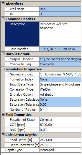
Input data type
Choose Single-phase data only, Two-phase data only or Single-phase and two-phase data according to what feedzone data you want to enter.
Enthalpy option:
The enthalpy calculation field relates to the values that will be stored in the enthalpy differences section of the TETRAD Wellbore Table. TETRAD can determine wellhead enthalpies as well as wellhead pressures from the data in the Wellbore Tables. Rather than explicitly using wellhead enthalpy values in the Wellbore Table for trilinear interpolation of the actual enthalpy value, TETRAD uses the enthalpy difference between wellbottom and wellhead.
The options are:
Depth increment and Number of retries:
The depth increment is used in just the same way as for any normal. However, unlike a normal discharge test simulation, WellSim may try the simulation again should it fail, due to the non-convergence of the solution. The benefit of this is that the TETRAD table should be as complete and as continuous as possible, and you do not want zero entries in the table except for cases where the flow would physically choke. In some cases the simulation may not converge, simply due to the choice of depth increment. Depending on the number of retries specified (which can be set to zero), WellSim will reproduce the unsuccessful simulation, but will use a smaller depth increment. At each retry, WellSim will multiply the depth increment by 0.67.
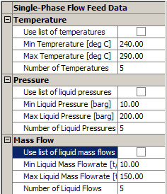
Enter the feedzone data. You can enter the feedzone data:
Enter a minimum, maximum and number of values here, because it is faster.
Enter this single-phase feedzone data:
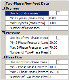
Enter this two-phase feedzone data:
Enter these well names into the Assigned well names:
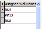
If there is more than one well with a similar geometry, feedzone depth and formation temperature then the same TETRAD table will apply to each well. WellSim lets you enter the applicable well names for each TETRAD table. WellSim does not check that the wells exist.
Click Check to check the data you have input. Here there is an error message:
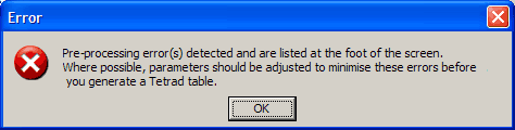
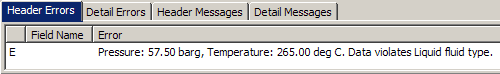
If error messages like this about the feedzone data indicate a combination of conditions that is physically impossible. You can either adjust a minimum or maximum until it does not give these errors when you click Check, or you can just ignore it and still Run the table. Here we'll ignore it.
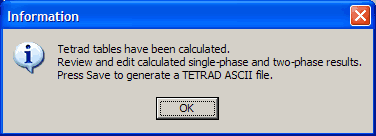
Click Run to calculate the wellhead data for the tables. At the end of a run WellSim displays a message to remind you that it has calculated the TETRAD table data, but it has not yet written the ASCII text file for TETRAD to disk yet:
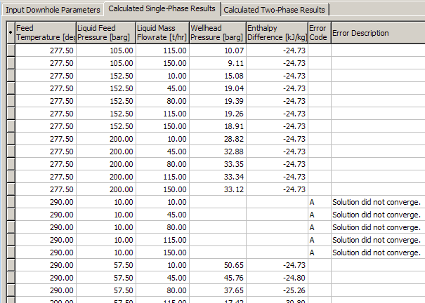
Click the tab Calculated single-phase results or Calculated two-phase results:
or
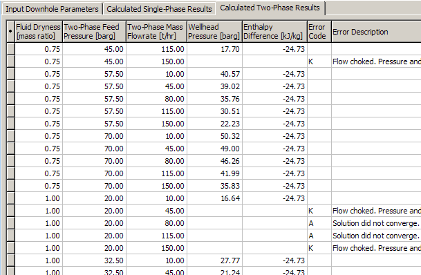
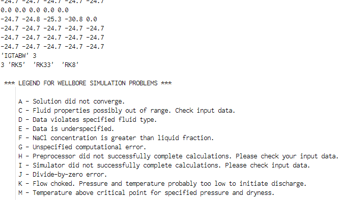
Look at the calculated results and check there are not too many errors. The error codes are:
| Code | Meaning |
|---|---|
| A | Solution did not converge |
| C | Fluid properties possibly out of range |
| D | Data violates specified fluid type |
| E | Data is underspecified |
| F | NaCl concentration is greater than liquid fraction: specifying dry or almost dry steam with salt concentration is not possible |
| G | Unspecified computational error |
| H | Preprocessor did not successfully complete calculations |
| I | Simulator did not successfully complete calculations |
| J | Divide-by-zero error |
| K | Flow choked: pressure and temperature probably too low to initiate discharge, or flowrate too high. |
| M | Temperature above critical point for specified pressure and dryness: WellSim tries to find a temperature that will result in the specified dryness at the specified temperature. |
In this tutorial, there are not too many errors. If your live data has too many errors then you might try to change the feed data until it doesn't give so many errors when you click Run:
Remember that the reason you are changing the feed data to reduce errors is mostly to decrease the number of BottomUp discharge calculations to be done; TETRAD will ignore any data points with such errors.
When you save the data set, you have the option of writing the calculated TETRAD data to a text file, for sending to TETRAD.
Click Save. WellSim shows where the text file will be written:
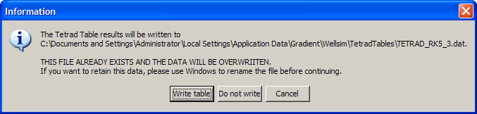
The message above also says that the text file already exists and it will be overwritten. To save an existing file, switch to the Windows Explorer, rename the existing file and switch back to WellSim to write the new text file.
If the calculated TETRAD results have errors, as they probably will, then WellSim asks what to do with them:
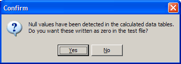
Yes to convert the error codes in the text file to zeroes, which TETRAD will ignore.No to leave the error codes in the file. Do not send such a file to TETRAD!In this tutorial click No so we can look at the errors.
Finally, WellSim confirms that it has written the text file, and gives its path:
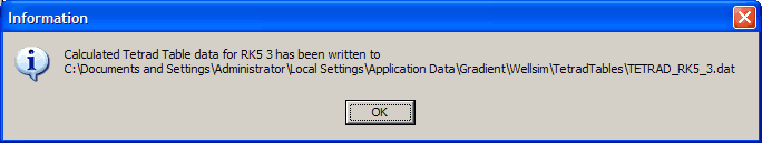
Note the path name (the folders and file name).
If you are writing more than one TETRAD table for a geothermal field to send to TETRAD, write each as described above, then use a text editor to join them together in one text file and send this file to TETRAD.
Use a text editor to open the ASCII text file path you noted above.
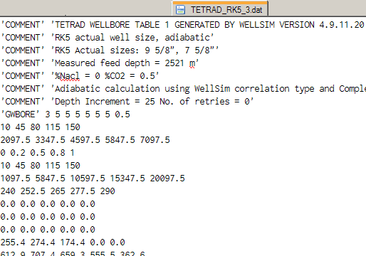
This has:
This has:
Note This tutorial file has the error codes in the lines of data, plus the legend of error codes. These must not be sent to TETRAD. To write an ASCII text file to send to TETRAD, click Yes to convert the error codes in the text file to zeroes and to not write the legend.
At TETRAD tables, tag the line you just entered and click the Detail table tab (for single-phase results).
Click Multiple graph.
You may now see an error like this, ignore it:
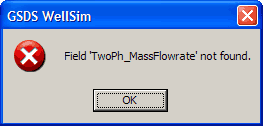 or
or 
Such errors happen when you change a TETRAD table's Multiple Graph from single and two-phase, or back, and the default independent axis now does not exist. Go to Settings and change the independent axis, as we do below.
Click Group.
Now move Liquid feed pressure and Feed temperature from Sort fields to Group fields:
Liquid feed pressure and Feed temperature.Click  to move these two fields to
 Group fields.
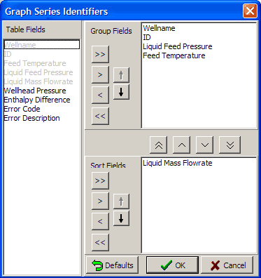
Finally click OK.
Click Settings. Change the axes and visible fields to:
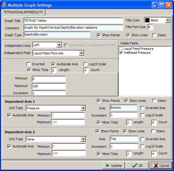
Finally click OK.
The graph is:
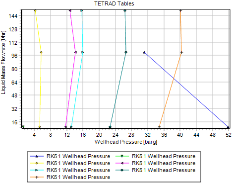
Note Group by Liquid feed pressure and Feed temperature as above to to see the variation of wellhead pressure with mass flow. Group by other fields to see different graphs, for example to see the variation of wellhead pressure with temperature, then group by pressure and mass flowrate.
Repeat the above steps, but this time:
Detail table 2 tab (for two-phase results).Group, move Dryness and Two-phase feed pressure and from Sort fields to Group fields.Two-phase mass flowrate.