Introduction
Tutorials
Getting familiar with GeoData Manager
Changing how GeoData Manager looks
Scenarios for using GeoData Manager
Data types and nodes
Help with data types and nodes
Getting familiar with GeoData Manager
Changing how GeoData Manager looks
Scenarios for using GeoData Manager
Help with data types and nodes
GeoData Manager has over 150 data types or nodes. This and subsequent sections of the help guide:
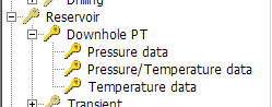
Show you how to choose the correct data type/node to use for entering and working with data. For example, the data type for results of downhole pressure logs is Pressure Data, which is in the Downhole PT category of the Reservoir category:
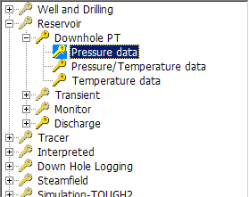
We write the nodes separated by colons, the above node is:
Reservoir: Downhole PT: Pressure Data
Give details of how to work with data of each data type/node.
Choose the correct data type category or node to use from the table below, according to the kind of data you want to work with
and follow the link in the table below to choose the correct data type to use.
| For this kind of data | Choose this category or node |
|---|---|
| Mechanical data for actual and planned wells and drilling | Wells and drilling |
| Any discharge test | See below |
| P, T and flow time-based data during development (downhole PT, transient monitor & discharge, also spinner) | Reservoir |
| The results of tracer tests (chemical & radioactive) | Tracer |
| Interpreted data for the geothermal system: | Interpreted |
| The results of down hole logging (not downhole T, P or flow logs) | Downholehole Logging |
| Pressure, temperature and flow time-based data collected during production | Steamfield |
| Power plant data and measurements: | Power Plant |
| Results of chemical analyses (geothermal fluid, soil, not rocks) | Chemistry |
| Geological data from wells & field sites (has rock properties & chemistry) | Geology |
| Geophysical data (resistivity, gravity, MT) | Geophysics |
GeoData Manager can work with external simulation applications:
| Application | Choose this category or node |
|---|---|
| TOUGH2 | Simulation - TOUGH2 |
| TETRAD | Simulation - TETRAD |
Data types used internally by GeoData Manager:
| Kind of data | Choose this category or node |
|---|---|
| Values that will appear in drop-down menus | Lookups |
| Cross sections across a geothermal system | Cross sections |
| Groups of wells or sample sites | Groups |
| Data integrity checks | Data Integrity Checks |
| Log of database transactions | Logs |
| Log of database upgrades | Read more |
Go to GeoData Manager's home window, click File, click Expand All Tree Nodes to see at the left of the window:
All the branches of the database tree - the dotted lines.
All the nodes of the database tree - the words.
The nodes at the tips of the tree's branches (on the right) correspond to data types and the nodes to the left of the tips correspond to data type categories, which are just convenient groups of data types. The database tree is presented to you like a tree (with branches and nodes), rather than a list of all the data types, for three main reasons:
To get to a particular data type, for example downhole pressure data for development wells, it is quicker to double-click Reservoir, then double-click Downhole PT, then click Pressure Data than to scroll through a list of about 150 data types and click one.
In several places, nodes at the tip of the branches are similar and you can work with all such nodes at the node to the left. For example:
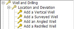
Enter a well as Vertical, Surveyed, Angled or Redrilled at the appropriate node. But to work with wells, you usually don't care what shape they are, and you can work with all wells, regardless of shape, at Location and Deviation:
Similarly, enter a downhole test as Pressure, Pressure/Temperature or Temperature at the appropriate node. But work with all such tests at Downhole PT:
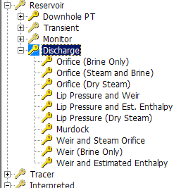
There are two kinds of discharge measurement, those where you enter flows directly and those that where you enter measurements from field instruments, for example weir levels or pressure diferences, and GeoData Manager calculates the flows. Enter the former at the node Discharge. Enter the latter at the appropriate sub-node of Discharge. Work with both kinds of discharges at the node Discharge:
Sometimes, two nodes display the same data, but the data is presented differently at each node. Use whichever node lets you work with the data more easily. For example in Geology there are two nodes for the core register:
Core Register - by Well This is a normal kind of node, for entering and working with core data.
Core Register - by Section This has a row in the header window for each core or cutting. Use this node to select and work with all cores easily.
Other similar pairs of nodes are:
In Chemistry: Fluids - by Sample Set and Fluids - by Sample.
In Geophysics: MT: Model and the subnode By Layers.
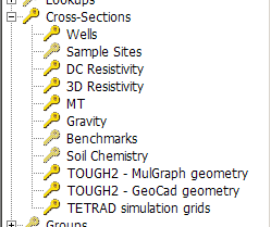
A cross section has two detail tables, the locations of the ends of the segments of the cross section and the sites associated with the cross section. Enter the locations of all cross sections at the node Cross-Sections. Enter the sites at the appropriate sub-node. Work with all cross sections at Cross-Sections:
A Mulgraph simulation grid at Simulation - TOUGH2: Grid - Mulgraph Geometry has several detail tables: Layers, Blocks, Vertices, Partial Layer and Vertex Order. Enter the grid header data at Grid - Mulgraph Geometry. Enter and work with the detail tables at the appropriate sub-node of Grid - Mulgraph Geometry:
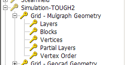
Note that in these cases you create a new data set at the higher node using New, then go to the sub-node and enter the detail data using Edit.
A site is the location of a field in space. GeoData Manager can find the location in space of every field in one of two ways:
Some data types are called sites and have a location. The sub-nodes of the node Cross-Sections are the data types that are sites (though the data at these sub-nodes does not show the location; you need to go to the data types themselves to see this). All sites are a single point (eg Chemistry: Sample Site) except for wells, which store the wellhead location and the deviation information.
For all other data types, you must enter a site as part of the header data, and GeoData Manager looks up the location of the site when required. For example, for a downhole pressure test, you enter a well for the test; GeoData Manager uses the depth of each measurement and the well's wellhead location and the deviation information to calculate or interpolate the location of that measurement down the well.
Note:
The fields in the P-Tree tab starting with Site define how a data set finds its location.
GeoData Manager stores all locations as map coordinates (Location E, Location N) and as degrees (longitude and latitude read more.
GeoData Manager can store discharge tests for four occasions:
Pressure drawdown tests on development wells:
These are transient tests made on discharging wells. We recommend that these tests are reserved for data from wells discharging at a fairly steady rate, thus giving a classic pressure drawdown response. Data from wells with varying discharge due to cycling or output adjustments, might be better entered as an ordinary discharge test, below.
Discharge tests for development wells:
If the well has a reasonably constant mass flow, it may be better entered as a pressure drawdown test, above.
If the well is discharged at a number of distinct flow rates, these can be entered as a single discharge test or a number of separate discharge tests. Even if a well is closed for a period within a discharge test, the pressure data during the shut-in can be included as part of the discharge test (with the flow rate set to zero), or as a separate monitoring test.
Discharge tests for a production wells
Reinjection measurements for a production wells
A discharge test's measurements can be either:
Direct measurements (or your calculations): of flows, enthalpy.
Indiect measurements: from field instruments, for example weir depth measurements and orifice plate pressure measurements.
When you enter a discharge test's results, you will normally not have measured every parameter, and GeoData Manager will calculate the others. There are about 20 kinds of discharge test, according to what parameters you have measured and weather you have direct or indirect measurements.
GeoData Manager does three kinds of calculation:
For any indirect flow measurements from instruments, calculate actual flow measurements.
From the the measured separation pressure plus any two of brine flow, steam flow, total mass flow or enthalpy, GeoData Manager calculates the other two fields.
For a specified well head pressure, total mass flow is not affected by separation pressure. You can look at the effect of changing separation pressure to something different from your measured one and GeoData Manager will recalculate the brine and steam flows, keeping the total mass flow the same.
Other, optional, fields to record measurements, for example Wellhead Pressure and Wellhead Temperature.
You can enter results from discharge tests through two separators. In this case, as described below, set Configuration to Double and use Weirbox ID (1 or 2) to distinguish the data from the two separators.
A discharge test's other fields include:
Measurement Depth: When you create a new discharge test you are required to enter this in the identifiers. Enter a depth if you have one, otherwise enter zero. You can use Order to hide this field in the header window if you don't use it.
Other, optional, fields to record measurements, for example Wellhead Pressure and Wellhead Temperature.
Pressure drawdown test fields:
Usually wellhead pressure is measured (although downhole measurements can be made), together with total mass flow. Discharge enthalpy can be measured and recorded for completeness but is not required for analysis.
Test Start Time and undisturbed pressure: As for all transient tests, the test start time defines the start of the transient event, in this case the start of discharge. The first (earliest) pressure measurement in the pressure table is assumed to be the undisturbed pressure, and differential pressures are calculated relative to this value. Note that measurements can occur before the test start time.
Mass Flow: Enter a value into all fields in the detail table even if the discharge is fairly constant and a typical value has been entered in the header data.
Separation Pressure: Leave blank if the well is being discharged to an atmospheric silencer, as it will be filled in automatically, calculated from the elevation of the well.
There are three cases; choose the appropriate one:
Editing or working with a discharge you have already entered.
Entering a new discharge when you have values of the flows and maybe enthalpy, for example when you have already calculated flows from field instrument measurements.
Entering a new discharge when you have indirect measurements of the flows, from field instruments, for example a weir level as an indication of brine flow.
| Occasion of discharge test | Go to this node |
|---|---|
| Pressure drawdown, development well | Reservoir: Pressure drawdown |
| Discharge test, development well | Reservoir: Discharge |
| Discharge test, production well | Steamfield: Production |
| Reinjection measurement, production well | Steamfield: Reinjection |
1 - Look in this table to find a value of FType to use:
| Phase | Kind of measurements you have | Value of FType |
|---|---|---|
| 1 | Brine flow and temperature | 1 |
| 2 | Steam & brine flow, separation pressure | 2 |
| 2 | Brine flow, enthalpy, separation pressure | B |
| 1 | Dry steam: flow, temperature, pressure or WHP | D |
| - | Incomplete Data | N |
| 2 | Steam flow, enthalpy, separation pressure | S |
| 2 | Total flow, enthalpy, separation pressure | T |
Note:
Choose FType = N if you are not entering all the required values yet. Later, when you enter the rest of the values, change FType to the correct value in the edit window.
Flows should be calculated from measurements at the specified separation pressure.
For single-phase discharges (FType = 1 or D), GeoData Manager will calculate enthalpy from well temperature or pressure measurements.
For measurements of enthalpy (FType = B, S or T), enthalpy should be calculated from measurements at the specified separation pressure. Fortunately, as discharge enthalpy usually does not vary much, you can use an estimated enthalpy if you don't know the actual value.
2 - Choose a node to use:
| Occasion of discharge test | Choose this node |
|---|---|
| Pressure drawdown, development well | Reservoir: Pressure drawdown |
| Discharge test, development well | Reservoir: Discharge |
| Discharge test, production well | Steamfield: Production |
| Reinjection measurement, production well | Steamfield: Reinjection |
3 - Go to the node you chose in step 2 above and start entering a new data set; at the first window (New Data Identifiers), select from the dropdown list the value of FType you chose in step 1 above.
1 - Choose a node to use:
| Occasion of discharge test | Choose this node |
|---|---|
| Pressure drawdown, development well | Reservoir: Pressure drawdown |
| Discharge test, development well | Reservoir: Discharge |
| Discharge test, production well | Steamfield: Production |
| Reinjection measurement, production well | Steamfield: Reinjection |
2 - Look in this table to choose the subnode to use:
| Phase | Kind of measurements you have | Choose this subnode |
|---|---|---|
| 1 | Brine: upstream & differential orifice pressures | Orifice (Brine Only) |
| 2 | Upstream & differential orifice pressures | Orifice (Steam and Brine) |
| in separated steam & brine lines | ||
| 1 | Steam: upstream & differential orifice pressures | Orifice (Dry Steam) |
| 2 | Lip pressure and weirbox measurement | Lip Pressure and Weir |
| 2 | Lip pressure & estimated enthalpy | Lip Pressure and Est. Enthalpy |
| 1 | Lip pressure for dry steam discharge | Lip Pressure (Dry Steam) |
| 2 | Upstream & differential orifice pressures (for Murdock's equation) | Murdock |
| 2 | Weirbox measurements for brine flow and upstream & differential steam orifice pressures | Weir and Steam Orifice |
| 1 | Weirbox measurements for a brine flow | Weir (Brine Only) |
| 2 | Weirbox measurements, estimated enthalpy | Weir and Estimated Enthalpy |
Note:
Depending on the subnode you choose, GeoData Manager will use the appropriate value for FType.
For single-phase discharges, GeoData Manager will calculate enthalpy from well temperature or pressure measurements.
For the subnode Orifice (Steam and Brine): If the flow varies between two-phase and single-phase, enter a zero value for the differential pressure of the phase (steam or brine) that stops flowing. If you have a NULL (blank) value, GeoData Manager this assume it has not been entered, and will not calculate the flows. If you enter a zero differential pressure, GeoData Manager will calculate enthalpy from the well temperature and the separation pressure.
3 - Go to the node you chose in step 1 above, choose the subnode of that node that you chose in step 2 above and start entering a new data set.
4 - At the at the first window (New Data Identifiers), the fields to enter may include:
Weir Code Select the type of weir you have. If Configuration (below) is Double, both weirs must be identical.
Well Status Type Select Discharge for a discharge to atmosphere or a silencer; Production for discharge to a separator above atmospheric pressure.
FType If you have lip pressure data, select a value of FType to choose the formula to calculate flows and enthalpy: H to use the Hiriart formula, L to use the James formula.
Configuration For when there is a weir to measure brine flow. Normally there is one weir; select Single. However, GeoData Manager can also use measurements when there are two separate lines from the well, with two weirs and perhaps two steam lines, each with their own instruments; select Double.
Primary Weir Data Select Weir Water Height or Weir Water Pressure depending on the type of weir you have. If Configuration (above) is Double, both weirs must be identical.
Test Enthalpy If the discharge requires an estimated enthalpy you can enter an optional default value here.
Click OK to go on to the edit window.
5 - At the edit window:
If measurements are from a weir, enter the weir specifications in the header data. If Configuration (above) is Double, both weirs must be identical, and you only enter one set of weir specications.
If Configuration is Single then when you click Check or Apply for the first time you might get an unexpected I message that Weirbox ID has been set to 1. Ignore this. The field Weirbox ID is normally hidden.
If Configuration is Double, enter the measurements like this:
a - The detail data for a discharge has a field Weirbox ID, which is hidden by default. If it is hidden, then before you enter any data: leave the edit window and return to the subnode you just left; click Order below the detail data and move Weirbox ID to the visible fields; then return to the edit window.
b - For each set of measurements made at the same date and time, enter two rows of data. For the first row, set Weirbox ID to 1 and enter data for the first weir and any associated steam line. For the second row, set Weirbox ID to 2 and enter data for the second weir and any associated steam line.